To prepare home plans for 3D exterior rendering, you must supply your visualization studio with a complete, coordinated document package: dimensioned floor plans for every level, all four orthographic facade elevations, a roof plan, section drawings, and a site plan – all delivered in native CAD format (DWG, DXF, or RVT) rather than scanned PDFs. Each document must be accompanied by a written materials specification schedule that references manufacturer product codes, finish types, and color values, alongside annotated photographic style references and defined camera view instructions. Every gap in this brief is a decision your rendering artist must make independently, and independent decisions are what cause revision cycles, delayed deliveries, and final images that do not accurately represent your approved design.
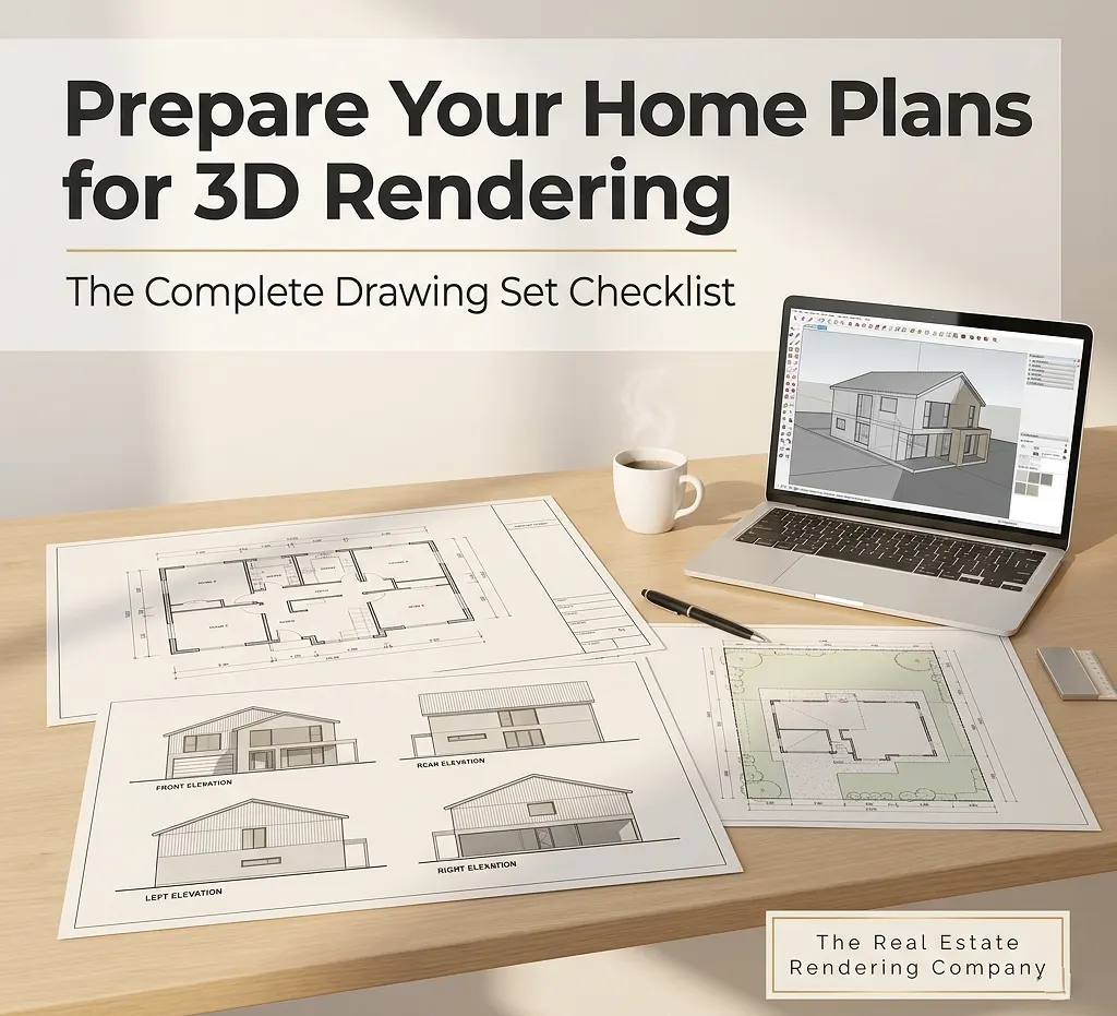
Whether you are a homeowner collaborating with a residential architect, a developer building a pre-sales marketing campaign, or a design professional preparing investor presentations, the preparation workflow is the same. This guide covers every step: which drawings are mandatory, which file formats your studio actually needs, how to write a materials specification that eliminates ambiguity, and the seven most costly preparation mistakes that consistently delay projects.
For developers and architects who need photorealistic, construction-accurate exterior images built to marketing and planning-approval standards, working with a dedicated real estate 3D rendering and architectural visualization service from the outset ensures your prepared documents are handled by specialists – not generalists.
Table of Contents
Why Your Rendering Brief Controls Everything
Before covering what to submit, it helps to understand the mechanism by which preparation quality determines rendering quality.
A 3D exterior rendering starts with interpretation, not software. Your rendering artist converts your two-dimensional documents into a three-dimensional digital scene, then layers materials, lighting, landscaping, and environmental context on top of that model to produce a photorealistic image.
Every element that is not specified in your brief gets decided by the studio. That is not always a problem – experienced studios make informed default decisions. But the more decisions you leave unspecified, the more revision rounds you will need when the first draft reflects the artist’s interpretation rather than your design intent.
Quick definition: A rendering brief is the complete package of technical drawings, editable files, written specifications, and visual references that you submit to a 3D visualization studio at the project start. It is the primary translation layer between your design intent and the studio’s output.
According to ArchiCGI’s exterior rendering workflow documentation, the foundation of every exterior project is always architectural drawings – floor plans, elevations, and sections that define building geometry – paired with lighting and mood references that communicate the desired atmosphere. Studios that receive both produce better results in fewer iterations.
The Complete Drawing Set: What Your Studio Actually Needs
1. Floor Plans – Every Level, Fully Dimensioned
Floor plans are the horizontal foundation of the 3D model. The modeling artist uses them to establish the building footprint, wall thickness, room layout, and the precise placement of every door and window opening before any vertical geometry is built.
Your floor plans must include:
- Accurate dimensions for every room, wall, and structural opening
- Door swing directions and window placement with head/sill height notations
- North orientation arrow and consistent drawing scale
- Explicit notation for level changes, steps, or split-floor conditions
- Separate, labeled layers for walls, doors, windows, fixtures, and annotations
For multi-story buildings, provide a separate, fully dimensioned plan for each floor level. Do not assume the upper levels can be inferred from the ground floor.
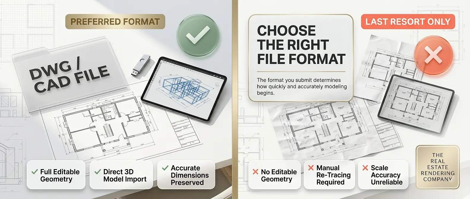
Recommended file format: DWG (AutoCAD) or RVT (Autodesk Revit). If only a PDF is available, it must be a vector export from CAD software – not a scan – with at least one confirmed real-world dimension annotated for scale reference.
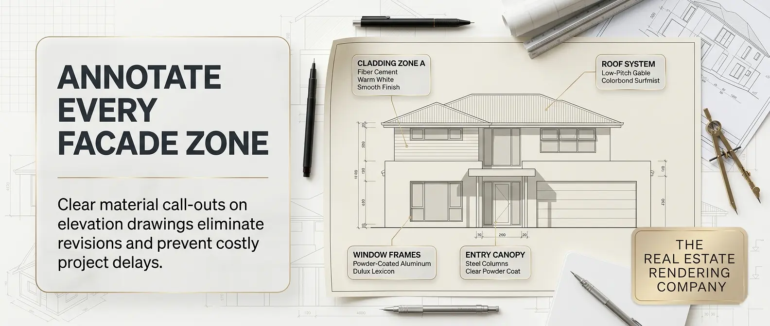
2. Facade Elevation Drawings – the Most Critical Input of All
If one drawing type determines the accuracy of your exterior rendering above all others, it is the facade elevation set. Exterior renderings are, by definition, views of your building’s exterior faces. Without dimensioned elevation drawings, your artist is making geometric assumptions about the building’s appearance.
You must provide all four orthographic elevations:
- North elevation
- South elevation
- East elevation
- West elevation
Each elevation drawing must clearly show:
- Overall building height from finished floor level to ridge, parapet, or eave
- Floor-to-floor heights on multi-story buildings
- Window and door dimensions, including mullion patterns, sill heights, and head heights
- Roof pitch with angle or ratio notation
- Overhang and soffit dimensions
- Cladding material zones, including transitions between different materials
- Architectural features: trim, cornices, banding, balustrades, and recessed elements
- Any canopies, pergolas, blade walls, or feature screens
Submitting floor plans without elevation drawings is the single most common cause of expensive rendering revision requests. Your artist cannot accurately model a roof line, a window proportion, or a cladding pattern from a plan view alone.
3. Roof Plan
The roof plan is separate from the floor plan and essential for any project with a non-trivial roof form: hip roofs, complex gable combinations, shed additions, dormers, or flat roofs with parapet and drainage details.
A complete roof plan includes:
- Ridge lines, valley lines, and hip lines with correct geometry
- Roof pitch notation for every plane
- Overhang and fascia dimensions
- Skylights, roof windows, chimneys, vents, and mechanical equipment
- Parapet heights and coping details on flat roofs
- Scupper or downpipe locations on low-slope roofs
For straightforward gable roofs on simple residential footprints, the roof form may be reconstructable from elevations and floor plans combined. For everything else, a dedicated roof plan is non-negotiable.
4. Section Drawings
Section cuts reveal vertical relationships that elevation drawings cannot fully communicate, particularly the relationship between floor levels, ceiling heights, structural elements, and exterior assembly buildups.
Include at minimum:
- One longitudinal section and one transverse section through the building
- Wall sections at material transitions and at non-standard assembly conditions
- Window and door head, sill, and jamb details if they are non-standard
- Any concealed gutter, parapet cap, or flush-frame window conditions that require specific modeling
5. Site Plan
The site plan provides the environmental context that makes an exterior rendering feel real rather than floating in a generic landscape. It establishes the building’s orientation on its lot, proximity to boundaries, driveway and pathway layouts, ground level changes, and existing landscape features.
For photorealistic marketing renders, accurate site context is often just as commercially important as the building itself. The site plan gives the artist the information needed to calculate accurate solar positioning, to model neighboring structures visible in the frame, and to place landscaping that reflects the actual environment.
Your site plan should include:
- True north orientation
- Property boundaries and dimensions
- Building footprint with setback dimensions
- Finished floor level relative to natural ground
- Driveway, path, and hardscape locations and materials
- Existing trees, shrubs, or landscape features to retain
- Any retaining walls, level changes, or grade conditions
File Format Guide: What to Send and Why It Matters
The format of your submitted drawings directly affects how quickly and accurately modeling can begin. This comparison table summarizes the formats that matter most.
Rendering File Format Comparison Table
| Format | Software Origin | Best Used For | Key Limitation |
|---|---|---|---|
| DWG | AutoCAD | Floor plans, elevations, site plans | Requires CAD-compatible viewer |
| DXF | AutoCAD / Universal | Cross-platform drawing exchange | Slightly less feature-rich than DWG |
| RVT | Autodesk Revit | BIM-coordinated projects, complex buildings | Studio must have a Revit license |
| SKP | SketchUp | Concept-stage massing models | Often requires significant cleanup |
| PDF (vector) | Any CAD export | Reference alongside CAD files | No editable geometry; slower to model from |
| PDF (scanned) | Physical drawings | Last resort only | Requires full manual re-digitization |
| JPG / PNG | Scans or renders | Visual reference only | Cannot serve as a modeling source |
Best practice: Always send DWG or RVT as the primary modeling source file. Include a high-resolution PDF as a visual reference to accompany it – never as a replacement for it.
As Rapid Renders notes in their studio briefing guide, the drawing format you provide determines how much of the studio’s time goes toward modeling versus rendering – and modeling time is where costs accumulate on anything beyond a simple project.
How to Write a Materials Specification That Eliminates Revisions
The 3D model provides the geometry. Materials provide the reality. Surface finishes, colors, textures, and reflectivity values determine whether a rendering looks convincingly photorealistic or generically computer-generated. Providing a precise materials schedule is one of the highest-leverage steps in the entire preparation process.
Materials Schedule: What to Specify for Every Surface
For all exterior wall cladding:
- Material type: brick, rendered masonry, fiber cement panel, timber weatherboard, stone, metal cladding, or composite
- Manufacturer name and product or color code
- Finish type: matte, satin, gloss, rough-textured, smooth, or board-formed
- Color reference: RAL code, NCS code, manufacturer color name, or hex value
- Bond or panel pattern for masonry and modular cladding
For windows and glazing:
- Frame material: uPVC, aluminum, timber, or steel
- Frame color with manufacturer reference
- Glazing type: clear float, low-e, tinted, reflective, or frosted
- Any mullion grid or internal bar pattern
For roofing:
- Material: concrete roof tile, clay tile, slate, metal standing seam, flat TPO membrane, or asphalt shingle
- Color and finish
- Ridge cap, fascia, and barge board details
For external joinery and metalwork:
- Garage door style, material, and color
- Entry door material, color, and hardware finish
- Any decorative screens, balustrades, or feature metalwork elements
For landscape and hardscape:
- Paving material and color: concrete, pavers, gravel, or timber decking
- Lawn treatment: turf, groundcover, or native planting
- Fencing type, material, and color
Supplement Your Schedule with Visual References
Written specifications alone can be ambiguous. Color names vary between manufacturers, and terms like “warm grey render” carry different meanings across studios. Always supplement your written schedule with:
- Manufacturer product images downloaded directly from official product pages
- Real-world photographs of the finish you want to replicate in-situ
- Annotated mood boards with specific elements circled or labeled
- Color chip scans or swatches with known code references
Style References and Camera View Specifications
Beyond drawings and materials, your rendering studio needs creative direction: what mood should each image convey, and from which vantage point should it be captured?
How to Define Your Camera Views
Rather than leaving camera placement to the artist, define your required views in advance. Receiving technically perfect renders of angles that do not serve your marketing or approval needs is one of the most common sources of client frustration on rendering projects.
Common exterior rendering view types:
- Hero shot (45-degree corner view): Shows two facade faces simultaneously. The most commercially effective angle for real estate marketing and the most frequently requested view type
- Street-level front elevation view: Low-angle perspective that mimics the experience of approaching the main entrance from the street
- Aerial or bird’s-eye view: Elevated angle that shows the full building in its site context; particularly useful for planning submissions and master-plan developments
- Rear garden view: View from the rear yard looking back at the rear elevation and outdoor living areas
- Feature detail close-up: Tight render of a specific architectural element: an entry canopy, balcony, facade panel system, or cladding detail
For each required view, specify:
- Approximate camera position (corner, front center, rear)
- Viewing direction and height (eye level, low angle, elevated)
- Time of day: golden hour (pre-sunset), midday, dusk/twilight, or night
- Season: full summer foliage, autumn, bare winter, or light snow
- Weather condition: clear blue sky, partly cloudy, or softly overcast
Suggested visual: A side-by-side comparison of the same building rendered at midday versus golden hour demonstrates how time-of-day specification alone transforms the emotional register of an image. Include this in client presentations when discussing rendering brief requirements.
Step-by-Step: How to Prepare Your Home Plans for 3D Rendering
Here is the complete preparation workflow, formatted as an actionable checklist from initial audit through final submission.
Step 1 – Audit Your Existing Drawing Set
Review every document you currently have before preparing your submission package. Ask yourself:
- Do I have all four facade elevations in CAD format?
- Are all floor plans fully dimensioned, at consistent scale, and current?
- Do my plans reflect the most recently approved design revision?
- Are CAD layers named, organized, and separated by element type?
Correct any dimensional inconsistencies before submitting. Errors in drawings propagate directly into the 3D model and are significantly more expensive to correct after modeling has begun than before.
Step 2 – Organize Files Into a Labeled Submission Package
Create a clearly structured folder before uploading or emailing files to your rendering studio. Disorganized submissions slow project starts and increase the risk of the artist working from an outdated revision.
Recommended folder structure:
[Project Name] - Rendering Brief
|
+-- 01_CAD Files
|   +-- Floor Plans (DWG)
|   +-- Elevations (DWG)
|   +-- Sections (DWG)
|   +-- Roof Plan (DWG)
|   +-- Site Plan (DWG)
|
+-- 02_PDF Reference Set
|   +-- All Plans Combined (PDF)
|
+-- 03_Materials
|   +-- Materials Schedule (PDF or Excel)
|   +-- Material Reference Images (folder)
|
+-- 04_Style References
|   +-- Exterior Mood Images (annotated)
|   +-- Lighting and Time-of-Day References
|
+-- 05_Camera Views
    +-- Camera View Instructions (annotated site plan or PDF)
Step 3 – Complete Your Materials Schedule
Using the guidance in the previous section, produce a written materials schedule for every exterior surface. Even approximate or provisional specifications are better than none – they give your artist a starting point and reduce clarifying questions that delay the project start.
Step 4 – Compile Annotated Style and Mood References
Select 5 to 10 high-quality images of completed exterior projects that represent the visual mood, material character, and architectural language you want your rendering to reflect. Annotate each reference with a note explaining the specific quality you are referencing: the quality of the evening light, the grout color on the brick, the landscaping density, or the camera angle.
Generic mood boards submitted without annotation force the artist to guess which element attracted you to each reference image.
Step 5 – Write a Short Project Context Brief
A single paragraph describing your project helps the artist make better-informed decisions about every element outside your explicit specifications, including neighboring architectural character, suburb context, target buyer demographic, and the intended commercial use of each image.
Include:
- Building type: single-family home, duplex, townhouse, apartment building, or commercial development
- Location and climate zone
- Target market or buyer profile
- Intended use of images: pre-sale marketing, planning approval submission, investor presentation, or social media
- Delivery deadline and revision round expectations
Step 6 – Final Check Against the Pre-Submission Checklist
Pre-Submission Checklist Table
| Document / Item | Required | Strongly Recommended |
|---|---|---|
| Floor plan – all levels, DWG | Yes | – |
| All 4 facade elevations, DWG | Yes | – |
| Roof plan, DWG | Yes | – |
| Section drawings, DWG | Yes | – |
| Site plan, DWG | Yes | – |
| PDF reference set (full plan set) | Yes | – |
| Written materials schedule | Yes | – |
| Material image references | – | Yes |
| Annotated style / mood references | Yes | – |
| Camera view specifications | Yes | – |
| Project context brief | – | Yes |
| Confirmed deadline and revision scope | Yes | – |
| Geographic location or coordinates | – | Yes |
Step 7 – Review, Confirm Revision Number, and Submit
Before sending, confirm that every CAD file is labeled with a revision number and date. Notify your studio immediately if you update any drawing after submission – and clearly mark the changes. Any rendering work begun on a superseded document may need to be restarted at additional cost.
7 Common Mistakes That Delay Your 3D Exterior Rendering Project
Even experienced architects and property developers submit rendering briefs that generate unnecessary back-and-forth. Here are the seven most frequent mistakes – and exactly how to avoid each one.
Mistake 1: Submitting Scanned PDFs Instead of CAD Files
A scanned PDF is not a modeling source. It requires the artist to manually trace every geometric element before modeling can begin, adding hours to the project and introducing transcription errors. Even a clean, vector PDF is a fallback option rather than a preferred input. Always provide DWG or RVT files as the primary submission.
Mistake 2: Missing Elevation Drawings
This is the most common and most expensive preparation gap in exterior rendering projects. Some clients submit floor plans under the assumption that an artist can infer the exterior appearance. They cannot – not accurately. Facade elevations are a mandatory input for exterior rendering, not an optional supplement.
Mistake 3: Dimensional Inconsistencies Between Plans and Elevations
If your floor plan shows a wall at 4,200mm but the corresponding elevation implies 4,500mm, the artist must make a judgment call. These conflicts often go undetected until the first draft render reveals a proportion problem, requiring a modeling revision that could have been eliminated by coordinating drawings before submission.
Mistake 4: No Materials Specification
Submitting architectural drawings without any materials information forces the artist to invent a material palette for your project. The result may look visually coherent – but it will not represent your actual design. Correcting materials after the first draft adds at least one to two business days to every revision cycle.
Mistake 5: Vague or Unannotated Style References
“Modern and clean” describes a very wide spectrum of visual outcomes. An unannotated mood board submitted without context is nearly as ambiguous. Use images that are specific to the visual quality you want, and annotate each one to explain which element attracted you to it.
Mistake 6: Submitting Outdated Plan Revisions
Always confirm that the documents you submit reflect the most current, coordinated design issue. If changes are made after submission, flag them explicitly to the studio and mark revised areas clearly. Rendering work completed on superseded plans is wasted work.
Mistake 7: Not Defining Camera Views Upfront
Agreeing on the number of views, the approximate camera positions, and the desired viewing directions before modeling begins prevents one of the most common sources of post-delivery dissatisfaction: receiving renders of angles that do not serve your intended purpose.
Expert Tips for Faster Turnaround and Better Results
These are the workflow habits that experienced developers and architects use to consistently get higher-quality exterior renders in fewer revision rounds.
1. Layer your CAD files with descriptive names. Name every layer clearly: WALL-EXT, WINDOW, DOOR, ROOF-PLANE, SITE-BOUNDARY. Clean layer organization is one of the most consistently appreciated inputs a modeling artist receives, and it directly shortens project start time.
2. Specify a geographic location and compass orientation. Photorealistic exterior renders calculate sun position from real-world geographic coordinates and time of day. Providing a city, suburb, or GPS coordinate pair allows accurate solar positioning, which determines the direction and quality of all shadows in the scene. This single specification significantly affects the realism and mood of your final image.
3. Draw everything at 1:1 real-world scale. Confirm that all DWG files are set to 1:1 scale using real-world units. Mixed scales across files – for example, a floor plan at 1:100 and elevations at 1:200 – are a reliable source of modeling proportion errors that are difficult to identify until the draft render stage.
4. Flag non-standard details explicitly. If your building includes a concealed gutter, a flush-frame window system, a recessed entry detail, or a folded roof plane, add a cloud annotation and a brief note directing the artist’s attention to it. Do not assume that a complex detail visible in section will be correctly interpreted without explicit guidance.
5. Include site photography. A photograph of the actual building site – showing neighboring houses, street character, mature trees, boundary fencing, and ground conditions – helps the artist build an environment that reads as authentic rather than generic. Even smartphone photographs taken from the street are far more useful than no reference at all.
6. Confirm output specifications before work begins. Agree with your studio upfront on final image dimensions (print-resolution at 300dpi, or screen-resolution at 72-96dpi), color space (sRGB for digital, AdobeRGB or CMYK for print), and whether layered PSDs are required for post-production editing. Resolving these details before rendering begins prevents last-minute format complications.
Understanding the technical distinction between 3D rendering and 3D modeling helps you communicate more precisely with your studio about which workflow stage you are reviewing and approving at each milestone.
What Happens After You Submit Your Plans: The Rendering Workflow
Understanding the studio’s production process helps you know when to expect your first draft and what feedback to prepare at each stage.
Stage 1 – Brief Review and 3D Modeling (Days 1 to 3)
The studio reviews your submission package, flags any missing information, and begins building the 3D model from your CAD files. Floor plans establish the building footprint and room geometry. Elevations drive the facade form and fenestration. Sections clarify vertical relationships and assembly conditions.
Stage 2 – Initial Draft Render (Days 3 to 5)
A lower-resolution draft image is produced showing the base model geometry, preliminary material assignments, and proposed camera angles. This is your primary quality gate: confirm that the geometry is accurate and that the camera views are correct before high-resolution production rendering begins.
Stage 3 – Materials, Lighting, and Environment Refinement (Days 5 to 7)
Following draft approval, materials are refined to match your specification schedule, lighting is configured for the specified time of day and season, landscaping and site elements are built out, and the full scene is optimized for final high-resolution rendering.
Stage 4 – Final Render Production and Delivery (Days 7 to 10)
High-resolution final images are rendered and post-produced. Post-production retouching typically includes sky replacement or enhancement, additional foliage compositing, vehicle and people placement for scale and lifestyle context, and final color grading. Files are delivered in agreed formats and dimensions.
Why Developers Invest in Properly Prepared Rendering Briefs
The effort required to prepare a complete, accurate rendering brief delivers commercial returns that extend well beyond the rendering project itself.
Developers who understand the full scope of what professional exterior visualization delivers invest proportionally more in the preparation stage – because they know that the images produced from a well-prepared brief perform better across every downstream use case.
The evidence is consistent: selling properties faster with 3D renderings is well-documented across residential, commercial, and mixed-use development categories. Buyers make faster, more confident purchasing decisions when they can evaluate a photorealistic, accurate exterior visualization rather than a line drawing or a generic computer image.
For commercial development projects specifically, the full scope of what professionally prepared exterior visualization delivers – from planning submissions through to investor presentations and pre-leasing campaigns – is covered in the 3D exterior rendering for commercial real estate FAQ.
Understanding why real estate developers use rendering services at every stage of the development lifecycle – from design development through to construction completion marketing – further reinforces why rendering brief quality is a direct commercial priority, not merely a technical one.
Rendering Software: What Professional Studios Use and Why It Matters
While you do not need to operate the same software as your rendering studio, understanding the tools involved helps explain why specific file formats are preferred and what level of photorealism is achievable at professional production quality.
Professional-grade exterior renderings are typically produced through a combination of:
- Autodesk 3ds Max: Industry-standard platform for 3D scene assembly, modeling, and camera setup
- V-Ray or Corona Renderer: Physics-based rendering engines that simulate real-world light transport – including global illumination, reflections, refractions, and subsurface scattering – to produce images indistinguishable from photographs
- Autodesk Revit: BIM-integrated platform used for design-phase modeling and increasingly for rendering on larger commercial and multi-residential projects
- Adobe Photoshop and Lightroom: Post-production tools for sky compositing, color grading, people and vehicle placement, and final image delivery
This production stack is explored in detail in the guide to the best real estate 3D rendering software – and it reinforces precisely why CAD file quality and drawing accuracy matter so much. The modeling artist’s work in 3ds Max or Revit is only ever as geometrically precise as the drawings you provide.
For transparent guidance on what professional exterior rendering projects cost at different scales, the real estate rendering price list covers residential, commercial, and multi-unit development categories.
Frequently Asked Questions: How to Prepare Home Plans for 3D Rendering
Q1: What is the minimum information needed to prepare home plans for 3D rendering?
The absolute minimum for an accurate exterior rendering is: dimensioned floor plans for every level, all four facade elevation drawings, and a roof plan – all in CAD format (DWG preferred). A basic materials specification and at least one style reference image are strongly recommended alongside these. Without elevation drawings, a geometrically accurate exterior render cannot be produced.
Q2: Can I submit hand-drawn or hand-sketched plans for a 3D exterior rendering?
Yes, but with important limitations. Hand sketches can inform early concept-stage renders, but they require the modeling artist to make many interpretive geometric decisions. This increases revision cycles and cost. For accurate, photorealistic results used in planning submissions or marketing campaigns, CAD-format drawings are always the correct input.
Q3: What file format is best when preparing home plans for 3D rendering?
DWG (AutoCAD) is the preferred format across most professional rendering studios. RVT (Autodesk Revit) is equally effective for BIM-coordinated projects. DXF is a widely compatible alternative. A vector PDF can serve as a visual reference alongside a CAD source file, but should never be the sole submitted document.
Q4: Do I need a site plan to prepare home plans for 3D rendering?
Yes. A site plan is essential for any render showing the building in its landscape or street context. It establishes cardinal orientation for solar positioning, defines the layout of driveways and pathways, and communicates
Preparation is the Discipline That Determines the Outcome
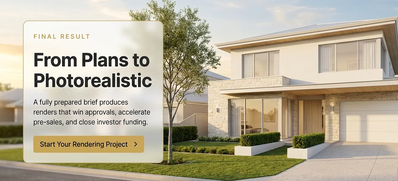
Learning how to prepare home plans for 3D rendering is not a bureaucratic step before the creative work begins. It is the creative work – the stage at which your design intent is either accurately communicated or left open to interpretation.
The studios that consistently produce the most impressive, marketing-grade exterior visualizations are not simply more talented. They are working from better briefs.
Submit complete, dimensioned CAD files for all four facade elevations, every floor level, the roof plan, and the site plan. Accompany them with a detailed materials specification schedule, annotated style and mood references, and clearly defined camera view instructions. When you do this, you give your rendering artist everything they need to translate your architectural intent into a photorealistic image – without guesswork, without unnecessary revision cycles, and on schedule.
The difference between a two-revision project and a ten-revision project almost always begins in the brief, not in the studio.
Ready to turn your fully prepared home plans into photorealistic exterior renders that accelerate planning approvals, close pre-sales faster, and win investor confidence? Work with The Real Estate Rendering Company to deliver construction-accurate, marketing-grade 3D visualizations from your first brief submission through to final image delivery.